Abstract
This paper presents a numerical study about the effects of chloride-induced corrosion on the service life of structures. A two-dimensional geometrically nonlinear mechanical model based on Finite Element Method (FEM) was developed for reinforced concrete structures. The corrosion initiation stage was evaluated by Fick's diffusion laws. The corrosion propagation was carried out by deterministic models based on Faraday's law. Pitting corrosion was simulated in the reinforcements by pit elements, distributed longitudinally on the steel rebars, which degrade the physical properties over time. The service life was determined by the crack width.Two parametric analyses were performed. In the first analysis, five models were created with a variablecover thickness and water/cement ratio (w/c). In the second analysis, the reduction in yield stress due to corrosion was considered.The results showed that the concrete cover thicknessand the w/c ratio significantly influence the service life. The reduction of the cover thickness from 30 mm to 25 mm resulted in 21.26% reduction in service life, whilethe increase in the w/c ratio from 0.50 to 0.55 caused 32.98% reduction in service life of the structural element analyzed.
Keywords:
Reinforced concrete structures; Chloride-induced corrosion; Pitting corrosion; Service life
Resumo
Neste artigo é apresentado um estudo numérico sobre os efeitos da corrosão induzida por cloreto na vida útil de elementos estruturais. Um modelo mecânico bidimensional geometricamente não linear baseado no Método dos Elementos Finitos (MEF) foi desenvolvido para a análise de estruturas de concreto armado. O estágio de iniciação da corrosão foi avaliado pelas leis de difusão de Fick. A propagação da corrosão foi realizada por modelos determinísticos baseados na lei de Faraday. A corrosão por pite foi simulada nas armaduras por elementos de pite, distribuídos longitudinalmente nas barras de aço, que degradam suas propriedades físicas ao longo do tempo. A vida útil foi determinada pela largura da fissura. Duas análises paramétricas foram realizadas. Na primeira análise, cinco modelos foram criados adotando diferentes cobrimentos e relação água/cimento (a/c). Na segunda análise considerou-se a redução da tensão de escoamento devido à corrosão. Os resultados mostraram que a espessura do cobrimento de concreto e a relação a/c influenciam significativamente na vida útil. A redução do cobrimento de 30 mm para 25 mm resultou em 21,26% de redução da vida útil, já o aumento da relação a/c de 0,50 para 0,55 ocasionou uma redução de 32,98% na vida útil do elemento estrutural analisado.
Palavras-chave:
Estruturas de concreto armado; Corrosão induzida por cloretos; Corrosão por pites; Vida útil de service
Introduction
The corrosion of reinforcement steel is the main pathological manifestation that affects reinforced concrete structures (OTIENO; BEUSHAUSEN; ALEXANDER, 2016aOTIENO, M.; BEUSHAUSEN, H.; ALEXANDER, M. Chloride-induced corrosion of steel in cracked concrete: part II: corrosion rate prediction models. Cement and Concrete Research , v. 79, p. 386-394, 2016a., 2016bOTIENO, M.; BEUSHAUSEN, H.; ALEXANDER, M. Chloride-induced corrosion of steel in cracked concrete: part I: Experimental studies under accelerated and natural marine environments. Cement and Concrete Research , v. 79, p. 373-385, 2016b.; CAO et al., 2019CAO, Y. et al. Critical chloride content in reinforced concrete - an updated review considering Chinese experience. Cement and Concrete Research, v. 117, p. 58-68, 2019.), motivating the development of studies related to service life. Such studies guide the development of mitigating and preventive actions during the design phase, improving durability and minimizing cost of rehabilitation. The costs of repairing and maintaining structures damaged by corrosion have substantially increased with the advance of the construction industry. The amount used for repair and rehabilitation of corroded structures is more significant in more technologically developed countries, and may assume values between 3.5% and 5.0% of Gross Domestic Product (GDP) (GENTIL, 2011GENTIL, V. Corrosão. 4. Ed. Rio de Janeiro: Editora LTC, 2011.; RIBEIRO, 2018RIBEIRO, D. V. (coord.). Corrosão e degradação em estruturas de concreto: teoria, controle e técnicas de análise e intervenção. 2. ed. Rio de Janeiro: Elsevier Brasil, 2018.).
Corrosion directly influences the structures` service life, which corresponds to the period that the structure is able to perform its functionality with safety, stability and comfort. In this sense, corrosion is divided into two stages: initiation and propagation (TUUTTI, 1982TUUTTI, K. Corrosion of steel in concrete. Stockholm: Swedish Cement and Concrete Research Institute Stockholm, 1982.; RAUPACH, 2006RAUPACH, M. Models for the propagation phase of reinforcement corrosion-an overview. Materials and Corrosion, v. 57, n. 8, p. 605-613, 2006.). The initiation stage is governed by the mass transport phenomena within the concrete and corresponds to the time elapsed until depassivation of the reinforcements. The corrosion of rebars occurs in the propagation stage, after depassivation of the steel rebar. In this work it is modeled the corrosion triggered by chloride ions, called pitting corrosion, which consists of an electrochemical process that attacks discrete spots of the rebar. Such corrosive process leads to the most severe scenario for the material integrity. The main deleterious effects that affect the structural mechanical behavior are: reduction of the steel cross-section; presence of internal pressures due to the rust layer; reduction or loss of adherence between steel and concrete; reduction of the steel yield stress; and stress concentration due to material discontinuities. The simultaneous action of all these effects directly interferes with structural stability, affecting its safety and performance (GONZALEZ et al., 1996GONZALEZ, J. A. et al. Some questions on the corrosion of steel in concrete: part I: when, how and how much steel corrodes. Materials and Structures, v. 29, n. 1, p. 40-46, 1996.; OTIENO; BEUSHAUSEN; ALEXANDER, 2011OTIENO, M. B.; BEUSHAUSEN, H. D.; ALEXANDER, M. G. Modelling corrosion propagation in reinforced concrete structures - a critical review. Cement and Concrete Composites , v. 33, n. 2, p. 240-245, 2011.; MICHEL et al., 2016MICHEL, A. et al. Propagation of steel corrosion in concrete: experimental and numerical investigations. Cement and Concrete Composites, v. 70, p. 171-182, 2016.).
Most studies of the corrosion initiation stage are related to the transport mechanisms of aggressive agents, in which the mass transport is strongly influenced by the porous network properties of the concrete cover. Based on the principles of mass transport, several deterministic models have been proposed to establish the initiation of chloride-induced corrosion (MIDGLEY; ILLSTON, 1984MIDGLEY, H. G.; ILLSTON, J. M. The penetration of chlorides into hardened cement pastes. Cement and Concrete Research , v. 14, n. 4, p. b546-558, 1984.; SAETTA; SCOTTA; VITALIANI, 1993SAETTA, A.; SCOTTA, R.; VITALIANI, R. Analysis of chloride diffusion into partially saturated concrete. Materials Journal, v. 90, n. 5, p. 441-451, 1993.; MANGAT; MOLLOY, 1994MANGAT, P. S.; MOLLOY, B. T. Prediction of long term chloride concentration in concrete. Materials and Structures , v. 27, n. 6, p. 338-346, 1994.). Among the various phenomena of mass transport, ionic diffusion stands out as the main transport mechanism of chloride ions and, therefore, the initiation stage can be consistently modeled considering it as an isolated mechanism (VU; STEWART, 2000VU, K. A. T.; STEWART, M. G. Structural reliability of concrete bridges including improved chloride-induced corrosion models. Structural Safety , v. 22, n. 4, p. 313-333, 2000.; VAL; CHERNIN; STEWART, 2009VAL, D. V.; CHERNIN, L.; STEWART, M. G. Experimental and numerical investigation of corrosion-induced cover cracking in reinforced concrete structures. Journal of Structural Engineering , v. 135, n. 4, p. 376-385, 2009.). Diffusion develops in the presence of a concentration gradient; thus, modeling of diffusion can be adequately approached by Fick's laws (STEWART, 2004STEWART, M. G. Spatial variability of pitting corrosion and its influence on structural fragility and reliability of RC beams in flexure. Structural Safety, v. 26, n. 4, p. 453-470, 2004. ; MEDEIROS, 2008MEDEIROS, M. H. F. Contribuição ao estudo da durabilidade de concretos com proteção superficial frente à ação de íons cloretos. São Paulo, 2008. 218 f. Tese (Doutorado em Engenharia Civil) - Escola Politécnica, Universidade de São Paulo, 2008.; GUZMÁN; GÁLVEZ; SANCHO, 2011GUZMÁN, S.; GÁLVEZ, J. C.; SANCHO, J. M. Cover cracking of reinforced concrete due to rebar corrosion induced by chloride penetration. Cement and Concrete Research , v. 41, n. 8, p. 893-902, 2011.; PELLIZZER; LEONEL; NOGUEIRA, 2018PELLIZZER, G. P.; LEONEL, E. D.; NOGUEIRA, C. G. Numerical approach about the effect of the corrosion on the mechanical capacity of the reinforced concrete beams considering material nonlinear models. IBRACON Structures and Materials Journal , v. 11, n. 1, p. 26-51, 2018.).
Modeling of the corrosion process is a great challenge. Several studies have been carried out to conceive mathematical models capable to describe the corrosion rate during the propagation stage (VU; STEWART, 2000VU, K. A. T.; STEWART, M. G. Structural reliability of concrete bridges including improved chloride-induced corrosion models. Structural Safety , v. 22, n. 4, p. 313-333, 2000.; LIU; WEYERS, 1998LIU, T.; WEYERS, R. W. Modeling the dynamic corrosion process in chloride contaminated concrete structures. Cement and Concrete Research , v. 28, n. 3, p. 365-379, 1998.; AHMAD; BHATTACHARJEE, 2000AHMAD, S.; BHATTACHARJEE, B. Empirical modelling of indicators of chloride-induced rebar corrosion. Journal of Structural Engineering, v. 27, n.3, p. 195-207, 2000.; YU et al., 2014YU, B. et al. Practical model for predicting corrosion rate of steel reinforcement in concrete structures. Construction and Building Materials , v. 54, n. 15, p. 385-401, 2014.). The reduction in the mechanical capacity of steel reinforcements was studied in several research groups. Andrade and Alonso (1996ANDRADE, C.; ALONSO, C. Corrosion rate monitoring in the laboratory and on-site. Construction and Building Materials, v. 10, n. 5, p. 315-328, 1996.) proposed a model based on Faraday's laws for the reduction of rebar diameter over time. Val and Melchers (1997VAL, D. V.; MELCHERS, R. E. Reliability of deteriorating RC slab bridges. Journal ofStructural Engineering, v. 123, n. 12, p. 1638-1644, 1997.) and Val, Stewart and Melchers (1998)VAL, D. V.; STEWART, M. G.; MELCHERS, R. E. Effect of reinforcement corrosion on reliability of highway bridges. Engineering Structures, v. 20, n. 11, p. 1010-1019, 1998. formulated models to estimate the residual steel area due to uniform and non-uniform corrosion, respectively. The simulation of internal pressures due to rust formation, leading to cracks of the concrete cover, was initially analyzed by Bažant (1979aBAŽANT, Z. P. Physical model for steel corrosion in concrete sea structures-theory. Journal of the Structural Division, v. 105, n. 6, p. 1137-1153, 1979a., 1979bBAŽANT, Z. P. Physical model for steel corrosion in concrete sea structures - application. Journal of the Structural Division , v. 105, n. 6, p. 1155-1166, 1979b.), using the theory of thick-walled cylinders. He assumed that the failure criterion was the appearance of a crack on the cylinder’s inner surface. Some followed these concepts and aimed at modeling non-uniform corrosion due to chloride ions. In particular, these researches focused at the reduction of rebar cross-section and propagation of corrosion products in reinforced concrete structures (PANTAZOPOULOU; PAPOULIA, 2001PANTAZOPOULOU, S. J.; PAPOULIA, K. D. Modeling cover-cracking due to reinforcement corrosion in RC structures. Journal of Engineering Mechanics , v. 127, n. 4, p. 342-351, 2001.; YUAN; JI, 2009YUAN, Y.; JI, Y. Modeling corroded section configuration of steel bar in concrete structure. Construction and Building Materials , v. 23, n. 6, p. 2461-2466, 2009.; BALAFAS; BURGOYNE, 2011BALAFAS, L.; BURGOYNE, C. J. Modeling the structural effects of rust in concrete cover. Journal of Engineering Mechanics, v. 137, n. 3, p. 175-185, 2011.).
With the development the Finite Element Method (FEM), notable advances have been achieved in the study of corrosion (REDAELLI et al., 2006REDAELLI, E. et al. FEM-models for the propagation period of chloride induced reinforcement corrosion. Materials and Corrosion , v. 57, n. 8, p. 628-635, 2006.; PAN; LU, 2011PAN, T.; LU, Y. Stochastic modeling of reinforced concrete cracking due to nonuniform corrosion: FEM-based cross-scale analysis. Journal of Materials in Civil Engineering, v. 24, n. 6, p. 698-706, 2011.; DU; CHAN; CLARK, 2006DU, Y. G.; CHAN, A. H. C.; CLARK, L. A. Finite element analysis of the effects of radial expansion of corroded reinforcement. Computers and Structures, v. 84, n. 13-14, p. 917-929, 2006.; CAO; CHEUNG, 2014CAO, C.; CHEUNG, M. M. S. Non-uniform rust expansion for chloride-induced pitting corrosion in RC structures. Construction and Building Materials , v. 51, p. 75-81, 2014.; LIBERATI et al., 2014LIBERATI, E. A. P. et al. Nonlinear formulation based on FEM, Mazars damage criterion and Fick’s law applied to failure assessment of reinforced concrete structures subjected to chloride ingress and reinforcements corrosion. Engineering Failure Analysis, v. 46, p. 247-268, 2014.). Improvement of complex models allowed a more realistic description of the materials` behavior. Nowadays, the Positional version of the FEM is proven to be a reliable alternative for geometrically nonlinear structural analysis (BONET et al., 2000BONET, J. et al. Finite element analysis of air supported membrane structures. Computer Methods in Applied Mechanics and Engineering, v. 190, n. 5, p. 579-595, 2000.; CODA; GRECO, 2004CODA, H. B.; GRECO, M. A simple FEM formulation for large deflection 2D frame analysis based on position description. Computer Methods in Applied Mechanics and Engineering , v. 193, n. 33/35, p. 3541-3557, 2004.), especially when associated with embedded techniques applied to model reinforced composites (VANALLI; PACCOLA; CODA, 2008VANALLI, L.; PACCOLA, R.; CODA, H. A simple way to introduce fibers into fem models. Communications in Numerical Methods in Engineering, v. 24, n. 7, p. 585-603, 2008.; SAMPAIO; PACCOLA; CODA, 2013SAMPAIO, M. S. M.; PACCOLA, R. R.; CODA, H. B. Fully adherent fiber-matrix FEM formulation for geometrically nonlinear 2D solid analysis. Finite Elements in Analysis and Design, v. 66, p. 12-25, 2013., 2015SAMPAIO, M. S. M.; PACCOLA, R. R.; CODA, H. B. A geometrically nonlinear FEM formulation for the analysis of fiber reinforced laminated plates and shells. Composite Structures , v. 119, p. 799-814, 2015.; PACCOLA; PIEDADE NETO; CODA, 2015PACCOLA, R. R.; PIEDADE NETO, D.; CODA, H. B. Geometrical non-linear analysis of fiber reinforced elastic solids considering debounding. Composite Structures, v. 133, n.1, p. 343-357, 2015.). The kinematic coupling for the embedded technique does not require matching of reinforcement and matrix meshes and does not increase the number of degrees of freedom. This approach is adopted in the mechanical modeling of the present work due to these advantages.
This study is an extension of the numerical model for reinforced concrete structures under uniform corrosion triggered by carbonation (FELIX, 2018FELIX, E. F. Modelagem da deformação do concreto armado devido à formação dos produtos de corrosão, São Carlos, 2018. Dissertação (Mestrado em Engenharia Civil) - Escola de Engenharia de São Carlos, Universidade de São Paulo, 2018.; FELIX et al., 2020FELIX, E. F. et al. Desenvolvimento e análise de um modelo numérico da expansão do concreto armado sujeito à corrosão uniforme. Revista ALCONPAT, v. 10, p. 300-316, 2020.). The references showed good results for both the representation of corrosion in cross-sections of reinforced concrete elements, by imposing a uniform stress field between steel and concrete, and in the evaluation of corrosion acting longitudinally on the reinforcement of structural elements. Cross section corrosion due to chloride ingress has been also modeled (RAMOS; CARRAZEDO, 2020RAMOS, E. S.; CARRAZEDO, R. Cross-section modeling of the non-uniform corrosion due to chloride ingress using the positional finite element method. Journal of the Brazilian Society of Mechanical Sciences and Engineering, v. 42, p. 548, 2020.).
Also, the same research group developed an Artificial Neural Network to evaluate the service life of reinforced concrete structures subject to generalized corrosion (FELIX et al., 2018FELIX, E. F. et al. Useful life analysis of reinforced concrete structure under uniform corrosion through ANN model coupled to the FEM. Revista ALCONPAT , v. 8, n. 1, p. 1-15, 2018.). The results pointed out the importance of the concrete cover in the initiation and propagation time of the corrosion by carbonation. It is noteworthy that the analyses were conducted assuming linear elastic materials. Based on these studies, this work focuses on the particular case of pitting corrosion. As main the novelty, in this article the coupling of the initiation and propagation models of chloride-induced corrosion to a two-dimensional Positional FEM numerical model with embedded steel rebars is presented, considering the physical nonlinearity for both materials, in the prediction of service life of reinforced concrete structural elements.
Thus, in this paper, a numerical model based on the Positional FEM for the analysis of the service life of reinforced concrete beams subjected to pitting corrosion is proposed. The mechanical fields are approximated by the FEM based on the positions` description, with exact kinematics. Two-dimensional finite elements describe the concrete matrix and truss elements are immersed to simulate the steel rebars. Kinematic coupling between the domains is based on embedded techniques, considering full adherence. The nonlinearities of concrete and steel are considered by mechanics of continuous damage and one-dimensional elastoplasticity, respectively. The corrosion initiation period is evaluated by Fick's diffusion laws. Corrosion propagation is performed using analytical models based on Faraday's law, penalizing the reinforcement cross-section over time. A simplified strategy is adopted to impose the pit`s position and distribution. The end of service life is established by the crack opening and width.
Modeling the chloride-induced corrosion
Initiation period
The initiation period of the chloride-induced corrosion on steel rebar is governed by mechanisms of mass transport in concrete, which define the rate that aggressive agents ingress the structural element and migrate through the concrete pores. Thus, the quality and thickness of the concrete cover are responsible for preserving the integrity of steel rebars. In this sense, the cover provides physical and chemical protection. It prevents direct contact with the external environment and it contributes to the stabilization of the passive film due to its alkalinity.
The transport mechanisms are influenced by the environment, by the concrete properties and by the mechanical loads. Temperature, solar incidence, rain and relative humidity of the air stand out among the environmental factors. Water/cement ratio, type of cement and its hydration process, curing and presence of additions are the main factors related to concrete properties. Finally, mechanical loads can also open up cracks due to tensile stresses, influencing the properties of mass transport (PELLIZZER, 2019PELLIZZER, G. P. Sobre a modelagem numérica da difusão de cloretos no concreto: uma abordagem pelo método dos elementos de contorno com aplicação de modelos de confiabilidade e otimização. São Carlos, 2019. 223 f. Tese (Doutorado em Engenharia Civil) - Escola de Engenharia de São Carlos, Universidade de São Paulo, 2019.).
Capillary pores in concrete provide transport system for the deteriorating agents. Nevertheless, the cracks in the Interfacial Transition Zone (ITZ) increase the permeability considerably, forming a preferential conduit to the deteriorating agents (RIBEIRO, 2018RIBEIRO, D. V. (coord.). Corrosão e degradação em estruturas de concreto: teoria, controle e técnicas de análise e intervenção. 2. ed. Rio de Janeiro: Elsevier Brasil, 2018.). Higher water-cement ratio increases capillary cavities and the size of voids.
The main mechanisms of chloride transport in concrete are capillary absorption and ionic diffusion. Capillary absorption takes place in the surface of the elements (10 to 20 mm) due to direct contact with aggressive agents (TUUTTI, 1996TUUTTI, K. Chloride induced corrosion in marine concrete structures. Durability of Concrete on Saline Environment, p. 81-93, 1996.; VAL; STEWART, 2003VAL, D. V.; STEWART, M. G. Life-cycle cost analysis of reinforced concrete structures in marine environments. Structural Safety , v. 25, n. 4, p. 343-362, 2003.). Ionic diffusion becomes predominant in the inner layers due to the electrolyte concentration in the conduction paths of the porous network. The maximum diffusivity is manifested in conditions of saturation between 60 to 80% (MEDEIROS, 2008MEDEIROS, M. H. F. Contribuição ao estudo da durabilidade de concretos com proteção superficial frente à ação de íons cloretos. São Paulo, 2008. 218 f. Tese (Doutorado em Engenharia Civil) - Escola Politécnica, Universidade de São Paulo, 2008.). Thus, in a simplified way, the corrosion initiation can be evaluated considering only diffusion (VU; STEWART, 2000VU, K. A. T.; STEWART, M. G. Structural reliability of concrete bridges including improved chloride-induced corrosion models. Structural Safety , v. 22, n. 4, p. 313-333, 2000.; VAL; CHERNIN; STEWART, 2009VAL, D. V.; CHERNIN, L.; STEWART, M. G. Experimental and numerical investigation of corrosion-induced cover cracking in reinforced concrete structures. Journal of Structural Engineering , v. 135, n. 4, p. 376-385, 2009.).
Following Vu and Stewart (2000)VU, K. A. T.; STEWART, M. G. Structural reliability of concrete bridges including improved chloride-induced corrosion models. Structural Safety , v. 22, n. 4, p. 313-333, 2000., Val and Stewart (2003)VAL, D. V.; STEWART, M. G. Life-cycle cost analysis of reinforced concrete structures in marine environments. Structural Safety , v. 25, n. 4, p. 343-362, 2003., Liberati et al. (2014LIBERATI, E. A. P. et al. Nonlinear formulation based on FEM, Mazars damage criterion and Fick’s law applied to failure assessment of reinforced concrete structures subjected to chloride ingress and reinforcements corrosion. Engineering Failure Analysis, v. 46, p. 247-268, 2014.) and Pellizzer, Leonel and Nogueira (2018PELLIZZER, G. P.; LEONEL, E. D.; NOGUEIRA, C. G. Numerical approach about the effect of the corrosion on the mechanical capacity of the reinforced concrete beams considering material nonlinear models. IBRACON Structures and Materials Journal , v. 11, n. 1, p. 26-51, 2018.), in this study Fick’s laws are adopted to estimate the depassivation time of the reinforcing steel. Therefore, the initiation stage is evaluated analytically by Fick’s laws, considering the phenomenon of chloride diffusion. Fick's first law model stationary diffusion, which is governed by the following differential Equation 1:
Where:
M is the diffusive molar mass flux;
D is the diffusion coefficient; and
C is the chloride concentration.
From the mass continuity, Fick’s second law can be derived directly, as follows (Equation 2):
Where D 0 is the diffusion coefficient, assumed constant.
Concrete properties such as the type of cement, compactness, curing and age of the concrete, as well as mineral additions influence the diffusion coefficient (FIGUEIREDO et al., 2014FIGUEIREDO, C. P. et al. The role of metakaolin in the protection of concrete against the deleterious action of chlorides. IBRACON Structures and Materials Journal , v. 7, n. 4, p. 685-708, 2014.; OLIVEIRA; CASCUDO, 2018OLIVEIRA, A. M.; CASCUDO, O. Effect of mineral additions incorporated in concrete on thermodynamic and kinetic parameters of chloride-induced reinforcement corrosion. Construction and Building Materials , v. 192, p. 467-477, 2018.). However, Bentz, Clifton and Snyder (1996BENTZ, D. P.; CLIFTON, J. R.; SNYDER, K. A. Predicting service life of chloride-exposed reinforced concrete. Concrete International, v. 18, n. 12, p. 42-47, 1996.) proposed a model that D0 (cm2/s) depends only on the water/cement ratio (w/c), as follows (Equation 3):
Considering a semi-infinite domain with uniform and constant chloride concentration over time, and disregarding the chlorides adhered to the concrete during mixing, the differential Equation 2 presents the following particular solution (Equation 4):
In which C 0 is the chloride concentration on the surface (kmol/m³) and erf is the Gauss error function. Thus, assuming C lim = C(x,t), the corrosion initiation time is written as (Equation 5):
Where x c is the thickness of concrete cover.
Following Liberati et al. (2014LIBERATI, E. A. P. et al. Nonlinear formulation based on FEM, Mazars damage criterion and Fick’s law applied to failure assessment of reinforced concrete structures subjected to chloride ingress and reinforcements corrosion. Engineering Failure Analysis, v. 46, p. 247-268, 2014.), Cao and Cheung (2014CAO, C.; CHEUNG, M. M. S. Non-uniform rust expansion for chloride-induced pitting corrosion in RC structures. Construction and Building Materials , v. 51, p. 75-81, 2014.) and Pellizzer, Leonel and Nogueira (2018PELLIZZER, G. P.; LEONEL, E. D.; NOGUEIRA, C. G. Numerical approach about the effect of the corrosion on the mechanical capacity of the reinforced concrete beams considering material nonlinear models. IBRACON Structures and Materials Journal , v. 11, n. 1, p. 26-51, 2018.), it is assumed that the diffusion coefficient and the surface concentration of chloride ions remain constant over time. For a review of non-constant diffusion coefficient and superficial chloride concentration, the reader is invited to consult the work of Dominicini and Calmon (2017DOMINICINI, W. K.; CALMON, J. L. Computational modeling for predicting corrosion initiation in reinforced concrete structures. IBRACON Structures and Materials Journal, v. 10, n. 6, p. 1205-1244, 2017.). Figure 1 shows the chloride concentration profile for the stationary and transient regime.

Propagation period
The chloride corrosion is an electrochemical process triggered by the destabilization of the passive oxide film, which is influenced by several factors such as the amount of electrolyte, the moisture content, the temperature and the availability of oxygen (MEIRA, 2017MEIRA, G. R. Corrosão de armaduras em estruturas de concreto: fundamentos, diagnóstico e prevenção. João Pesssoa: Editora IFPB, 2017.). It induces pitting corrosion, reducing rebar cross-section and steel yield stress.
In this paper, the reduction of reinforcement cross-section follows the model proposed by Yuan and Ji (2009YUAN, Y.; JI, Y. Modeling corroded section configuration of steel bar in concrete structure. Construction and Building Materials , v. 23, n. 6, p. 2461-2466, 2009.) based on experimental results. They proposed that the corroded cross-section takes the form of a semi-ellipse, in which the reduction of the radius is given by (Equation 6):
Where:
ust is the corroded layer thickness;
Rst is the rebar initial radius;
p is the pit depth; and
θ is the angle that describes the semi-elliptical surface, where 0 ≤ θ ≤ π.
The pit growth follows the proposal of Val, Stewart and Melchers (1998VAL, D. V.; STEWART, M. G.; MELCHERS, R. E. Effect of reinforcement corrosion on reliability of highway bridges. Engineering Structures, v. 20, n. 11, p. 1010-1019, 1998.), which is based on Faraday's laws and is an adaptation of the proposal of Andrade, Alonso and Rodríguez (1989ANDRADE, C.; ALONSO, C.; RODRÍGUEZ, J. Remaining Service Life of Corroding Structures. Report IABSE Symposium Durability of Structures, Lisboa, p. 359-364, 1989.). Therefore, the pit depth is written as follows (Equation 7):
Where:
p is the pit depth (mm);
icorr is the corrosion current density (μA/cm2);
tp is the propagation time (years); and
R is a probabilistic constant that relates the maximum and average pit depth, equals 5.08 according to Stewart (2004STEWART, M. G. Spatial variability of pitting corrosion and its influence on structural fragility and reliability of RC beams in flexure. Structural Safety, v. 26, n. 4, p. 453-470, 2004. ).
An empirical model is employed for the corrosion current density proposed by Vu and Stewart (2000VU, K. A. T.; STEWART, M. G. Structural reliability of concrete bridges including improved chloride-induced corrosion models. Structural Safety , v. 22, n. 4, p. 313-333, 2000.) (see also Val, Chernin and Stewart (2009VAL, D. V.; CHERNIN, L.; STEWART, M. G. Experimental and numerical investigation of corrosion-induced cover cracking in reinforced concrete structures. Journal of Structural Engineering , v. 135, n. 4, p. 376-385, 2009.), Liberati et al. (2014LIBERATI, E. A. P. et al. Nonlinear formulation based on FEM, Mazars damage criterion and Fick’s law applied to failure assessment of reinforced concrete structures subjected to chloride ingress and reinforcements corrosion. Engineering Failure Analysis, v. 46, p. 247-268, 2014.) and Muthulingam and Rao (2015MUTHULINGAM, S.; RAO, B. N. Non-uniform corrosion states of rebar in concrete under chloride environment. Corrosion Science, v. 93, p. 267-282, 2015.)). It only requires two parameters - the water/cement ratio and the concrete cover thickness - easily obtainable, although it is proposed for ambient temperatures close to 20ºC and relative humidity close to 75%. They proposed an exponential decrease in the corrosion current over time given by (Equation 8):
Thus, considering that only half section is exposed to chloride ingress, the residual area of the cross section (A res ) is written as (Equation 9):
Corrosion promotes chemical changes in the crystalline network of the metal and development of voids and defects in the microscopic structure of the steel, degrading the mechanical properties over time. Du, Chan and Clark (2006DU, Y. G.; CHAN, A. H. C.; CLARK, L. A. Finite element analysis of the effects of radial expansion of corroded reinforcement. Computers and Structures, v. 84, n. 13-14, p. 917-929, 2006.) developed an empirical model to represent the reduction in the steel yield stress based on experimental results, which is written as follows (Equation 10):
Where:
fy,corr is the yield stress of corroded rebar;
fy is yield stress of the uncorroded rebar; and
Qcorr is the rebar corrosion current state (%).
The corrosion current state may also be found by the rebar corroded and initial cross-section, as follows (Equation 11):
Mechanical modeling of reinforced concrete structures
Positional FEM applied to composite solids
Concrete matrix is discretized by two-dimensional triangular finite elements. Steel rebars are modeled by truss elements that are kinematically embedded in the matrix, allowing to simulate fibers reinforced composite structures. A Positional version of the FEM is used, employing a total Lagrangian description that considers the geometrically exact structural behavior. The principle of stationary total potential energy is applied for equilibrium and the Newton-Raphson procedure in the solution of the nonlinear system. The kinematic coupling procedure is detailed in Figure 2.
Nodal parameters of the reinforcement elements are written in function of the nodal parameters of the matrix elements, preserving the number of degrees of freedom. Thus, the reinforcement and matrix meshes are independent, that is, they do not require nodal coincidence. Stiffness and internal forces of trusses elements are calculated and then addressed to the degrees of freedom of the matrix elements in which the truss nodes are contained, as seen in Figure 2. Shape functions of the matrix elements at the position of the truss node are employed to evaluate each kinematic contribution. For complete description of the kinematic coupling, the reader is invited to consult Vanalli, Paccola and Coda (2008)VANALLI, L.; PACCOLA, R.; CODA, H. A simple way to introduce fibers into fem models. Communications in Numerical Methods in Engineering, v. 24, n. 7, p. 585-603, 2008., Radtke, Simone and Sluys (2010RADTKE, F. K. F.; SIMONE, A.; SLUYS, L. J. A computational model for failure analysis of fibre reinforced concrete with discrete treatment of fibres. Engineering Fracture Mechanics, v. 77, n. 4, p. 597-620, 2010., 2011RADTKE, F. K. F.; SIMONE, A.; SLUYS, L. J. A partition of unity finite element method for simulating non linear debonding and matrix failure in thin fibre composites. International Journal for Numerical Methods in Engineering, v. 86, n. 4-5, p. 453-476, 2011.), Sampaio, Paccola and Coda (2013SAMPAIO, M. S. M.; PACCOLA, R. R.; CODA, H. B. Fully adherent fiber-matrix FEM formulation for geometrically nonlinear 2D solid analysis. Finite Elements in Analysis and Design, v. 66, p. 12-25, 2013.) and Paccola, Piedade Neto and Coda (2015)PACCOLA, R. R.; PIEDADE NETO, D.; CODA, H. B. Geometrical non-linear analysis of fiber reinforced elastic solids considering debounding. Composite Structures, v. 133, n.1, p. 343-357, 2015., which present the mathematical developments for fibers reinforced domains using FEM. More information about the FEM based on positions can be found in Coda (2018)CODA, H. B. O método dos elementos finitos posicional: sólidos e estruturas - não linearidade geométrica e dinâmica. São Carlos: EDUSP, 2018..
Isotropic damage model
Continuous theory of damage based on thermodynamics of irreversible processes is used to evolve the nonlinear mechanical behavior of concrete, the mechanical degradation due to the evolution of microcracking. Reduction of the material stiffness is considered by damage variables calculated from the elongation state, penalizing the mechanical properties. In this paper, the scalar damage model proposed by Mazars (1984MAZARS, J. Application de la mécanique de l’endommagement au comportement non linéaire et à la rupture du béton de structure. Paris, 1984. 283 f. Tese (Doutorado em Engenharia Civil) - Université Paris 6, 1984.) is adopted, which admits the following set of hypotheses:
-
plastic strains are completely neglected;
-
damage evolution occurs only by elongations;
-
the damage is isotropic, that is, a scalar damage variable uniformly degrades all directions of the material; and
-
the beginning of the damage is verified only when a limit elongation is reached.

In the scalar damage model, an equivalent strain variable is introduced to measure the elongation state in a Representative Volume Element (RVE), given by (Equation 12):
Where (εi )+ are the positive principal strains. The damage criterion is defined by (Equation 13):
Where ε lim is the maximum strain recorded in strain evolution history.
At the beginning of the solution process, it is assumed that ε lim = ε d0 , where ε do is the maximum tensile strain of concrete. The formulation requires an incremental evolution of the constitutive model. Therefore, the evolution of the damage is written in infinitesimal form, and the following conditions are valid (Equations 14 and 15):
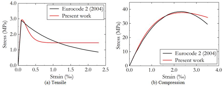
Equation 14 and 15 represent the conditions of complementarity and consistency, given by f dD = 0 and dfdD = 0. Term F (Ɛ eq, d(Ɛ eq )+) is a continuous positive function of the equivalent strain. Mazars` damage model is able to describe the asymmetric behavior of concrete uniaxial stress-strain curves by introducing damage variables D T and D C (see Equations 18 and 19). Figure 3 shows the uniaxial tensile and compressive behavior of concrete, described by damage variables. Thus, function F is decomposed into two parts, as follows (Equations 16 and 17):
Where AT , BT , Ac and BC are parameters of Mazar`s damage model, which can be obtained by monoaxial experimental tests.
Integrating FT and Fc functions for monotonically increasing loads, the damage variables result in (Equations 18 and 19):
A single scalar damage variable can be obtained from the linear combination of parameters DT and DC to analyze the multiaxial state of stress, as proposed by Perego (1989PEREGO, M. Damage of brittle materials: constitutive models, analysis by finite element method and applications. Milan, 1989. Thesis (Doctorate in Civil Engineering) - Politecnico de Milano, Milano, 1989.). It is required to initially evaluate the principal Cauchy stress and decompose into two parts, as follows (Equations 20 and 21):
The associated strain vectors Ɛi T and Ɛi C are calculated using generalized Hooke’s Law, according to the following expressions (Equations 22 and 23):
Where Ec is Young’s modulus and 𝜈 is Poisson’s ratio.
Thus, the scalar damage variable for the multiaxial case is written as (Equation 24):
Where 0 ≤ α ≤ 1, 0 ≤ αC ≤ 1 and αT + αC = 1. αT and αC are given by (Equations 25 and 26):

In which ƐV is the volumetric strain, given by (Equation 27):
At last, effective or damage Young’s modulus (ẼC ) is obtained as (Equation 28):
One-dimensional elastoplasticity
An elastoplastic model with positive linear isotropic hardening is considered for steel rebars, as shown in Figure 4. Parts L, H and U represent, respectively, loading, hardening and unloading stages.
An additive decomposition of the total strain (Ɛ results in elastic (Ɛe ) and plastic (Ɛp ) parts, as expressed in Equation 29. Thus, axial stress is determined by Equation 30, where 𝔼 is the modulus of Elasticity.
The incremental evolution is required by the constitutive model. In this sense, the Equations 29 and 30 are rewritten in infinitesimal form:
Yield criterion is defined in Equation 33, where k is the isotropic hardening modulus, σe is the material yield stress and α is the accumulated plastic strain, given by Equation 34:
The infinitesimal plastic strain dƐp is written as (Equation 35):
Where dλ is the infinitesimal plastic strain modulus and sign(σ) is the signum function of the stress, where sign(σ) = 1 if σ > 0 and sign(σ) = -1 if σ ≤ 0.
Equation 35 enforces that dλ = | dƐ p |. Deriving Equation 34, dα = | dƐ p |. From that (Equation 36):
It is now possible to write the conditions of complementarity and consistency, given respectively by f dλ = 0 and df dλ = 0. Assuming df = 0 and the consistency condition, the variation of the yield criterion is written as (Equation 37):
Thus, using Equations 32, 35 and 36 (Equation 38):

From Equations 38 and 35, plastic strain is determined as (Equation 39):
Finally, imposing Equation 39 in Equation 32, the increase in stress due to the strain increase is calculated as (Equation 40):
There Ec k / (Ec + k) stands for the tangent elastoplastic modulus for the hardening phase. To consider a perfect elastoplastic behavior, a null value must be assigned to k.
Results and discussions
Two examples are discussed in this section to evaluate the proposed formulation. The first example demonstrates the accuracy of the mechanical formulation applied to reinforced concrete structures. The structural behavior of a column with eccentric load, geometric imperfection and physical nonlinearity is evaluated, and results are compared with numerical and experimental values available in some references. Once validated, a chloride-induced corroded reinforced concrete beam is simulated. Service life considering both corrosion initiation and propagation is evaluated. A parametric study is evaluated, verifying the influence of each parameter of the implemented model.
Verification the mechanical model
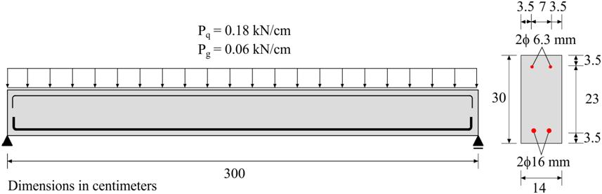
In the first example, the numerical formulation for nonlinear analysis of reinforced concrete structures is validated. The example consists of a column with eccentric load with an initial geometric imperfection, following experimental tests made by Espion (1993ESPION, B. Benchmark examples for creep and shrinkage analysis computer programs, creep and shrinkage of concrete. In: RILEM PROCEEDINGS. London: E&FN Spon, 1993.). Geometric properties and finite element mesh are shown in Figure 5. The concrete matrix was modeled with 960 triangular elements with cubic approximation, and reinforcements were discretized by 900 truss linear elements. Displacement control loading were imposed with increments of 0.12 mm on the top of the column, reading the resulting force.
Concrete is assumed isotropic, with Young’s modulus of Ec = 3360 kN/cm² and Poisson’s ratio of 𝜈 = 0.20. For steel rebars, a linear elastic, perfectly plastic model with Ec = 21000 kN/cm², v = 0.30, fe = 46.50 kN/cm² and k = 0 were adopted. For Mazars` damage model, the parameters were calibrated using Equation 18 and 19, following stress-strain curves presented by Parente Junior et al. (2014)PARENTE JUNIOR, E. et al. Material and geometric nonlinear analysis of reinforced concrete frames. IBRACON Structures and Materials Journal , v. 7, n. 5, p. 879-904, 2014., according to Eurocode 2 (COMITÉ…, 2004COMITÉ EUROPÉEN DE NORMALISATION. Eurocode 2: EN 1992-1-1: design of concrete structures: part 1-1: general rules and rules for buildings. Brussels, 2004.). The following set of parameters were obtained: Ɛd0 = 8.65 x 10⁻⁵, AT = 0.50, BT = 9000, Ac = 1.20 and Bc = 1500. Figure 6 shows the reference and calibrated curves obtained for concrete under tensile and compressive stresses. The curves are generic, valid for any column section
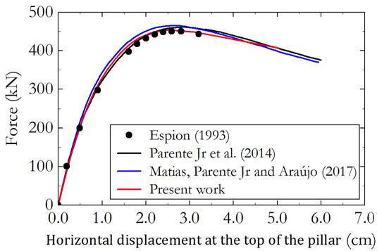
Analysis is interrupted by a sudden reduction in the stiffness due to localization of damage at the base of the column. Figure 7 shows the horizontal displacement in left corner on the top of the column as a function of the eccentric vertical force. The results are quite close to the experimental procedure developed by Espion (1993ESPION, B. Benchmark examples for creep and shrinkage analysis computer programs, creep and shrinkage of concrete. In: RILEM PROCEEDINGS. London: E&FN Spon, 1993.) and the numerical results presented by Parente Junior et al. (2014)PARENTE JUNIOR, E. et al. Material and geometric nonlinear analysis of reinforced concrete frames. IBRACON Structures and Materials Journal , v. 7, n. 5, p. 879-904, 2014. and Matias, Parente Junior and Araújo (2017MATIAS, B. S.; PARENTE JUNIOR, E.; ARAÚJO, T. D. P. Utilização do modelo constitutivo de Mazars na análise não linear estática de pórticos planos de concreto armado. In: IBERO-LATIN AMERICAN CONGRESS ON COMPUTATIONAL METHODS IN ENGINEERING, 38., Florianópolis, 2017. Anais ENT#091;…ENT#093; Florianópolis, 2017.). While the experimental maximum force was 450.19 kN, the proposed formulation achieved 454.00 kN, a difference of only 0.82%. Besides, both numerical references used a corotational formulation with cross-section integration by slicing method, achieving 460.56 kN and 465.01 kN for the maximum force, respectively.


Therefore, the calibration process of the damage parameters by normative instruments has proven to be a viable alternative in the absence of experimental data. Due to the development of large displacements, this example reveals the accuracy of the mechanical model, in which the effects of physical and geometric nonlinearities occur simultaneously. The results obtained were consistent with references, showing its applicability in the analysis of reinforced concrete structures.
Analysis of service life due to pitting corrosion
In the second example, the service life of a reinforced concrete simply supported beam under chloride-induced corrosion is evaluated. Two parametric analysis are performed to evaluate the importance of cover thickness, w/c ratio and whether reduction of yield stress should be considered in the analysis.
The concrete beam was designed following NBR 6118 (ABNT, 2014ASSOCIAÇÃO BRASILEIRA DE NORMAS TÉCNICAS. NBR 6118: projeto de estruturas de concreto. Rio de Janeiro, 2014.) to adequately resist shear forces and bending moments. Serviceability requirements are also ensured under service loads of a usual residential building. The beam was designed to support moderate exposure class related to environment (CAA II). Although it is not directly related to chlorides, it is something like XD1 class designation for EN 206 (BRITISH…, 2013BRITISH STANDARDS INSTITUTION. EN 206: concrete: specification, performance, production and conformity. Brussels, 2013.) (Corrosion induced by chloride other than sea water with moderate humidity). The following design parameters were then assumed:
-
cover thickness (c) of 30 mm;
-
w/c ratio of 0.50;
-
characteristic strength of concrete (fck) of 20 MPa; and
-
steel yield stress (fe) of 500 MPa.
Notice that, for CAA II, standard NBR 12655 (ABNT, 2015ASSOCIAÇÃO BRASILEIRA DE NORMAS TÉCNICAS. NBR 12655: concreto de cimento Portland: preparo, controle, recebimento e aceitação. Rio de Janeiro, 2015.) requires fck of 25 MPa, nevertheless a more severe scenario was imposed. Geometric properties and static configuration of the structural element are shown in Figure 8. Besides, a uniformly distributed dead load of Pg = 0.06 kN/cm and a live load of Pq = 0.18 kN/cm are considered.
The concrete matrix was modeled with 720 triangular elements with cubic approximation, and reinforcements were discretized by 663 truss linear elements. This level of refinement allowed qualitative assessment of the crack evolution. The largest crack width is verified at the bottom center of the beam due to tensile stresses, allowing entry of aggressive agents. Furthermore, the reduction in the steel cross-section in the midspan is the most unfavorable scenario for safety of the structural element. Therefore, pitting corrosion is imposed in the lower reinforcement at the bottom center. For this, it is proposed to create pit elements, which initially have the same properties as the steel rebars but the cross-section is updated according to the corrosion evolution. These elements simulate the formation of pits resulting from chloride-induced corrosion. Thus, 20 pit elements were uniformly distributed, spaced about two rebar diameters, and they size one rebar diameter. Figure 9 shows the finite element mesh, highlighting the position of the pit elements.
The following physical properties are adopted for concrete:
-
Ec = 3005.275 kN/cm²;
-
v = 0.20;
-
fctk,inf = 0.1547 kN/cm²;
-
Ɛd0 = 5.1476 x 10⁻⁵;
-
AT = 1.00;
-
BT = 11000;
-
AC = 0.70; and
-
BC = 1600.
Damage parameters were obtained as previous examples, fitting Equations 18 and 19. For steel rebars, a linear elastic, perfectly plastic model with EC = 21000 kN/cm², v = 0.0, fe = 50 kN/cm² and k = 0 wase adopted.


Finite element mesh and pit elements position in the central third of the lower reinforcement
Two analyses were carried out to evaluate the service life. In the first analysis, five models were created for different cover thickness and w/c ratio, as follows:
-
Model 1: Cover 30 mm and w/c = 0.50;
-
Model 2: Cover 25 mm and w/c = 0.50;
-
Model 3: Cover 20 mm and w/c = 0.50;
-
Model 4: Cover 30 mm and w/c = 0.45; and
-
Model 5: Cover 30 mm and w/c = 0.55.
Load are applied in twenty steps. Afterwards, corrosion initiation was stablished by Fick’s second law. The corrosion propagation was then simulated by increments of 1 year, until reaching the end of service life, which was established in terms of crack opening and crack width. All standards establish limits to crack width that do not compromise service conditions and structural performance. Brazilian standard NBR 6118 (ABNT, 2014ASSOCIAÇÃO BRASILEIRA DE NORMAS TÉCNICAS. NBR 6118: projeto de estruturas de concreto. Rio de Janeiro, 2014.) specifies maximum crack width value according to the exposure classes. Since moderate exposure class (CAA II) is adopted, the maximum crack width (wk ) is 0.3 mm, given by (Equation 41):
Where:
ϕi is the rebar diameter;
ni is the surface conformation coefficient equal to 2.25 for ribbed rebars;
σsi is the tensile stress of the evaluated steel rebar; and
Esi is Young's modulus of steel, fct,m is the concrete's average tensile strength, given by fct,m = 0.3(fck )2/3, and ρcr is the rate of steel in relation to the area of the region of involvement.
A constant chloride content of 0.9% on the surface of the structural element is imposed, according to Helene (1993HELENE, P. R. L. Contribuição ao estudo da corrosão em armaduras de concreto armado, São Paulo, 1993. 231 f. Tese (Livre Docência) - Escola Politécnica, Universidade de São Paulo, São Paulo, 1993.), for concretes with fck between 20 and 30 MPa and w/c between 0.48 and 0.68, exposed to salt spray. A critical chloride content of 0.4% was assumed for depassivation, according to Medeiros (2008MEDEIROS, M. H. F. Contribuição ao estudo da durabilidade de concretos com proteção superficial frente à ação de íons cloretos. São Paulo, 2008. 218 f. Tese (Doutorado em Engenharia Civil) - Escola Politécnica, Universidade de São Paulo, 2008.). Thus, employing Fick’s second law of diffusion, the chloride concentration on the surface of the reinforcement rebars over time are shown in Figure 10, for some cover thickneses and w/c ratio. Figure 10 shows a high sensitivity on both parameters. As expected, the chloride concentration in the reinforcement is more intense as cover is thinner (Figure 10a). Critical content is achieved after 7.91, 11.41 and 15.47 years for covers of 20, 25 and 30 mm, respectively. Similarly, Figure 10b shows greater adhesion of chlorides on the surface of rebars as w/c ratio increases. Critical content is achieved after 9.08, 15.47 and 26.57 years for w/c of 0.55, 0.50 and 0.45, respectively.
Once the chloride threshold is reached, the propagation stage is initiated and cracks develop further. Figure 11 shows the crack width evolution for different cover thicknesses and w/c ratios. In the corrosion initiation stage, only small cracks due tensile stresses are developed and do not compromise service conditions and structural performance. After corrosion begins, concrete cover and w/c ratio greatly influence the rate that cracks grow. The propagation stage took 9, 11 and 13 years for concrete covers of 20, 25 and 30 mm, respectively, to reach the maximum crack width of 0.3 mm (see Figure 11a). For w/c of 0.55, 0.50 and 0.45, propagation stage last 10, 13 and 17 years, respectively, until the maximum crack width was found (Figure 11b).
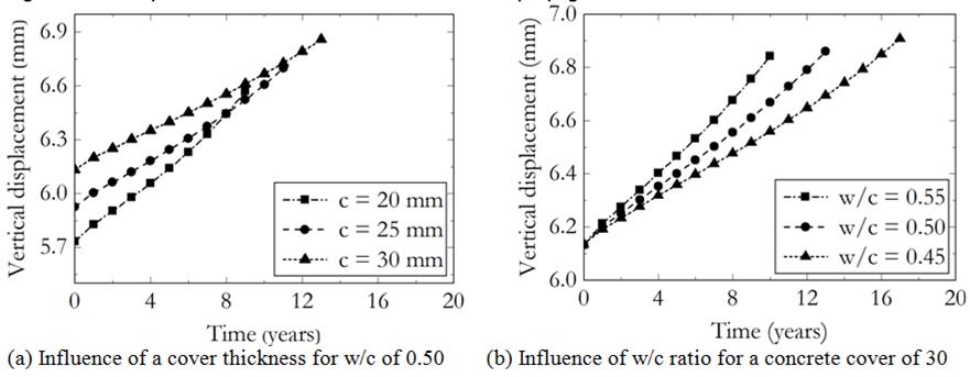
Another consequence of corrosion is the increase of vertical displacement of the beam midspan. The initial displacement due to only distributed loads may vary because the cover thickness leads to different moments of inertia. Moreover, it is noticed that creep and shrinkage strains are not considered in this example. Figure 12 shows the evolution of the beam midspan vertical displacement until the end of service life, for some scenarios. Midspan deflection is barely increased due to corrosion, and corresponds to 14.61%, 13.03% and 11.85% of the initial deflection calculated for cover thickness of 20, 25 and 30 mm, respectively. This indicates that vertical deflection is not the best way to validate the serviceability limit state for structures under corrosion.
Figure 13 shows the distribution of mechanical damage due to service loads and increased by corrosion, for a concrete cover of 30 mm and w/c of 0.50. The damage is increased overall, but especially in the midspan where pits were enforced.
Figure 14 shows the evolution of normal stresses in the reinforcement. There is a quite pronounced increase in the tensile stress in the reinforcement due to the reduction of cross section promoted by pit corrosion. Nevertheless, yielding was not achieved as stresses remained below 50 kN/cm².


The reduction in the cross section of the pit element due to corrosion is shown in Figure 15. The horizontal scale in Figures 15 to 20 was kept the same for easier comparison and analysis. The rate of corrosion is more pronounced at the beginning of the propagation stage, right after depassivation of the steel. At end of service life, cross section was reduced about 70.21%, 67.46% and 65.11% for cover thicknesses of 20, 25 and 30 mm, respectively. For w/c of 0.55, 0.50 and 0.45, the reduction was 67.37%, 65.11% and 64.24%, respectively.
Results are summarized in Tables 1 and 2, which show the influence of the cover thickness and w/c ratio on the beam`s service life. Table 1 shows that, for smaller covers, the propagation stage corresponds to most of the service life. Otherwise, the initiation stage is more pronounced for larger concrete covers. Table 2 shows that initiation stage is highly influenced by w/c ratio. An increase of w/c ratio from 0.45 to 0.55 reduces the initiation time by 65.83% and the service life by 57.19%.
A second analysis was performed, considering the same scenarios as the previous analysis, but a reduction of yield stress due to corrosion is now considered. In this analysis, the crack width opening did not reach the established limit of 0.30 mm, as shown in Figure 16, in any scenario. According to Equation 41, the crack width is proportional to the tensile stress of the reinforcement which is reduced after yielding. Thus, the crack width is reduced, indicating that the Brazilian standard NBR 6118 (ABNT, 2014ASSOCIAÇÃO BRASILEIRA DE NORMAS TÉCNICAS. NBR 6118: projeto de estruturas de concreto. Rio de Janeiro, 2014.) is unable to correctly simulate if corrosion and yield stress reduction are imposed.
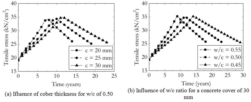
This behavior may also be observed when the yield stress and the midspan tensile stress is plotted along the corrosion propagation, as seen in Figure 17 and 18. Figure 17a shows the reduction of yield stress for different cover thickness, and Figure 17b shows the reduction of yield stress for different w/c ratios. Similar behavior is observed, depending only on the corrosion rate. Figure 18 shows that the tensile stresses at the pit elements have a sudden yet expected decrease due yielding.


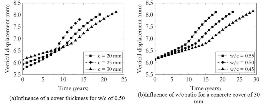
Figure 19 and 20 bring up the variation of maximum vertical displacement at the midspan and the reduction of the cross section of reinforcement for this second analysis, respectively. Notice in Figure 19 that, once yielding begins, the vertical deflection is intensified due to the reduction of the rebars cross section. It also reduces the second moment of area (cross sectional moment of inertia), as well as yielding.However, thevertical deflection is still below the limits established by Brazilian standard (L/250) NBR 6118 (ABNT, 2014ASSOCIAÇÃO BRASILEIRA DE NORMAS TÉCNICAS. NBR 6118: projeto de estruturas de concreto. Rio de Janeiro, 2014.). In the case of reduction of reinforcement, see Figure 20, asimilar profile to the previous analysis is obtained (Figure 15).
The analysess show that Brazilian standard NBR 6118 (ABNT, 2014ASSOCIAÇÃO BRASILEIRA DE NORMAS TÉCNICAS. NBR 6118: projeto de estruturas de concreto. Rio de Janeiro, 2014.) might be used for the analysis of service life of structures under corrosion if the yield stress remains constant. However, if the yield stress decays along thecorrosion propagation, and since the crack width is related to the reinforcement tensile stresses, the standard formulation may mislead to the cracks` closure. Figure 21 corroborates to this inconsistency showing the reduction of the crack width with the evolution of plastic strain.


Conclusions
In this paper a mechanical model for simulation of reinforced concrete structures under pitting corrosion was presented. A coupled formulation to simulate the corrosion initiation and propagation stages with nonlinear mechanical model was proposed and validated. The following conclusionswere drawn:
-
the nonlinear mechanical model based on the coupling of the Positional version FEM with Mazars` damage model and the one-dimensional elastoplastic model is proven to be reliable in the analysis of reinforced concrete structures. The results obtained in example 1 presented a good agreement with the references. The maximum force differed only 0.82% from the experimental value;
-
the second example indicates that the corrosion propagation stage has significant participation in the service life of the structure. Thus, the structural element is able to maintain its characteristics of safety and functionality for a reasonable period of time after the depassivation of the steel rebars;
-
the concrete cover thickness and the w/c ratio significantly influenced the service life. According to example 2, the reduction of the cover thickness from 30 mm to 25 mm resulted in 21.26% reduction in service life. The w/c ratio was more sensitive, in which an increase from 0.50 to 0.55 caused 32.98% reduction in service life; and
-
Brazilian standard NBR 6118 is capable to provide consistent results for the evaluation of service life of concrete structures under corrosion by the analysis of crack opening width. Nevertheless, if the decrease of rebar yield stress is considered, unfeasible results are attained.
Acknowledgments
The research supported by the Brazilian National Council for Scientific and Technological Development (CNPq 133981/2018-5, 310564/2018-2 and 428762/2018-2) is gratefully acknowledged. This study was also financed in part by the Coordenação de Aperfeiçoamento de Pessoal de Nível Superior - Brasil (CAPES) - Finance Code 001.
References
- AHMAD, S.; BHATTACHARJEE, B. Empirical modelling of indicators of chloride-induced rebar corrosion. Journal of Structural Engineering, v. 27, n.3, p. 195-207, 2000.
- ANDRADE, C.; ALONSO, C. Corrosion rate monitoring in the laboratory and on-site. Construction and Building Materials, v. 10, n. 5, p. 315-328, 1996.
- ANDRADE, C.; ALONSO, C.; RODRÍGUEZ, J. Remaining Service Life of Corroding Structures. Report IABSE Symposium Durability of Structures, Lisboa, p. 359-364, 1989.
- ASSOCIAÇÃO BRASILEIRA DE NORMAS TÉCNICAS. NBR 12655: concreto de cimento Portland: preparo, controle, recebimento e aceitação. Rio de Janeiro, 2015.
- ASSOCIAÇÃO BRASILEIRA DE NORMAS TÉCNICAS. NBR 6118: projeto de estruturas de concreto. Rio de Janeiro, 2014.
- BALAFAS, L.; BURGOYNE, C. J. Modeling the structural effects of rust in concrete cover. Journal of Engineering Mechanics, v. 137, n. 3, p. 175-185, 2011.
- BAŽANT, Z. P. Physical model for steel corrosion in concrete sea structures-theory. Journal of the Structural Division, v. 105, n. 6, p. 1137-1153, 1979a.
- BAŽANT, Z. P. Physical model for steel corrosion in concrete sea structures - application. Journal of the Structural Division , v. 105, n. 6, p. 1155-1166, 1979b.
- BENTZ, D. P.; CLIFTON, J. R.; SNYDER, K. A. Predicting service life of chloride-exposed reinforced concrete. Concrete International, v. 18, n. 12, p. 42-47, 1996.
- BONET, J. et al. Finite element analysis of air supported membrane structures. Computer Methods in Applied Mechanics and Engineering, v. 190, n. 5, p. 579-595, 2000.
- BRITISH STANDARDS INSTITUTION. EN 206: concrete: specification, performance, production and conformity. Brussels, 2013.
- CAO, C.; CHEUNG, M. M. S. Non-uniform rust expansion for chloride-induced pitting corrosion in RC structures. Construction and Building Materials , v. 51, p. 75-81, 2014.
- CAO, Y. et al. Critical chloride content in reinforced concrete - an updated review considering Chinese experience. Cement and Concrete Research, v. 117, p. 58-68, 2019.
- CODA, H. B. O método dos elementos finitos posicional: sólidos e estruturas - não linearidade geométrica e dinâmica. São Carlos: EDUSP, 2018.
- CODA, H. B.; GRECO, M. A simple FEM formulation for large deflection 2D frame analysis based on position description. Computer Methods in Applied Mechanics and Engineering , v. 193, n. 33/35, p. 3541-3557, 2004.
- DOMINICINI, W. K.; CALMON, J. L. Computational modeling for predicting corrosion initiation in reinforced concrete structures. IBRACON Structures and Materials Journal, v. 10, n. 6, p. 1205-1244, 2017.
- DU, Y. G.; CHAN, A. H. C.; CLARK, L. A. Finite element analysis of the effects of radial expansion of corroded reinforcement. Computers and Structures, v. 84, n. 13-14, p. 917-929, 2006.
- ESPION, B. Benchmark examples for creep and shrinkage analysis computer programs, creep and shrinkage of concrete. In: RILEM PROCEEDINGS. London: E&FN Spon, 1993.
- COMITÉ EUROPÉEN DE NORMALISATION. Eurocode 2: EN 1992-1-1: design of concrete structures: part 1-1: general rules and rules for buildings. Brussels, 2004.
- FELIX, E. F. et al. Desenvolvimento e análise de um modelo numérico da expansão do concreto armado sujeito à corrosão uniforme. Revista ALCONPAT, v. 10, p. 300-316, 2020.
- FELIX, E. F. et al. Useful life analysis of reinforced concrete structure under uniform corrosion through ANN model coupled to the FEM. Revista ALCONPAT , v. 8, n. 1, p. 1-15, 2018.
- FELIX, E. F. Modelagem da deformação do concreto armado devido à formação dos produtos de corrosão, São Carlos, 2018. Dissertação (Mestrado em Engenharia Civil) - Escola de Engenharia de São Carlos, Universidade de São Paulo, 2018.
- FIGUEIREDO, C. P. et al. The role of metakaolin in the protection of concrete against the deleterious action of chlorides. IBRACON Structures and Materials Journal , v. 7, n. 4, p. 685-708, 2014.
- GENTIL, V. Corrosão. 4. Ed. Rio de Janeiro: Editora LTC, 2011.
- GONZALEZ, J. A. et al. Some questions on the corrosion of steel in concrete: part I: when, how and how much steel corrodes. Materials and Structures, v. 29, n. 1, p. 40-46, 1996.
- GUZMÁN, S.; GÁLVEZ, J. C.; SANCHO, J. M. Cover cracking of reinforced concrete due to rebar corrosion induced by chloride penetration. Cement and Concrete Research , v. 41, n. 8, p. 893-902, 2011.
- HELENE, P. R. L. Contribuição ao estudo da corrosão em armaduras de concreto armado, São Paulo, 1993. 231 f. Tese (Livre Docência) - Escola Politécnica, Universidade de São Paulo, São Paulo, 1993.
- LIBERATI, E. A. P. et al. Nonlinear formulation based on FEM, Mazars damage criterion and Fick’s law applied to failure assessment of reinforced concrete structures subjected to chloride ingress and reinforcements corrosion. Engineering Failure Analysis, v. 46, p. 247-268, 2014.
- LIU, T.; WEYERS, R. W. Modeling the dynamic corrosion process in chloride contaminated concrete structures. Cement and Concrete Research , v. 28, n. 3, p. 365-379, 1998.
- MANGAT, P. S.; MOLLOY, B. T. Prediction of long term chloride concentration in concrete. Materials and Structures , v. 27, n. 6, p. 338-346, 1994.
- MATIAS, B. S.; PARENTE JUNIOR, E.; ARAÚJO, T. D. P. Utilização do modelo constitutivo de Mazars na análise não linear estática de pórticos planos de concreto armado. In: IBERO-LATIN AMERICAN CONGRESS ON COMPUTATIONAL METHODS IN ENGINEERING, 38., Florianópolis, 2017. Anais ENT#091;…ENT#093; Florianópolis, 2017.
- MAZARS, J. Application de la mécanique de l’endommagement au comportement non linéaire et à la rupture du béton de structure. Paris, 1984. 283 f. Tese (Doutorado em Engenharia Civil) - Université Paris 6, 1984.
- MEDEIROS, M. H. F. Contribuição ao estudo da durabilidade de concretos com proteção superficial frente à ação de íons cloretos. São Paulo, 2008. 218 f. Tese (Doutorado em Engenharia Civil) - Escola Politécnica, Universidade de São Paulo, 2008.
- MEIRA, G. R. Corrosão de armaduras em estruturas de concreto: fundamentos, diagnóstico e prevenção. João Pesssoa: Editora IFPB, 2017.
- MICHEL, A. et al. Propagation of steel corrosion in concrete: experimental and numerical investigations. Cement and Concrete Composites, v. 70, p. 171-182, 2016.
- MIDGLEY, H. G.; ILLSTON, J. M. The penetration of chlorides into hardened cement pastes. Cement and Concrete Research , v. 14, n. 4, p. b546-558, 1984.
- MUTHULINGAM, S.; RAO, B. N. Non-uniform corrosion states of rebar in concrete under chloride environment. Corrosion Science, v. 93, p. 267-282, 2015.
- OLIVEIRA, A. M.; CASCUDO, O. Effect of mineral additions incorporated in concrete on thermodynamic and kinetic parameters of chloride-induced reinforcement corrosion. Construction and Building Materials , v. 192, p. 467-477, 2018.
- OTIENO, M. B.; BEUSHAUSEN, H. D.; ALEXANDER, M. G. Modelling corrosion propagation in reinforced concrete structures - a critical review. Cement and Concrete Composites , v. 33, n. 2, p. 240-245, 2011.
- OTIENO, M.; BEUSHAUSEN, H.; ALEXANDER, M. Chloride-induced corrosion of steel in cracked concrete: part II: corrosion rate prediction models. Cement and Concrete Research , v. 79, p. 386-394, 2016a.
- OTIENO, M.; BEUSHAUSEN, H.; ALEXANDER, M. Chloride-induced corrosion of steel in cracked concrete: part I: Experimental studies under accelerated and natural marine environments. Cement and Concrete Research , v. 79, p. 373-385, 2016b.
- PACCOLA, R. R.; PIEDADE NETO, D.; CODA, H. B. Geometrical non-linear analysis of fiber reinforced elastic solids considering debounding. Composite Structures, v. 133, n.1, p. 343-357, 2015.
- PAN, T.; LU, Y. Stochastic modeling of reinforced concrete cracking due to nonuniform corrosion: FEM-based cross-scale analysis. Journal of Materials in Civil Engineering, v. 24, n. 6, p. 698-706, 2011.
- PANTAZOPOULOU, S. J.; PAPOULIA, K. D. Modeling cover-cracking due to reinforcement corrosion in RC structures. Journal of Engineering Mechanics , v. 127, n. 4, p. 342-351, 2001.
- PARENTE JUNIOR, E. et al. Material and geometric nonlinear analysis of reinforced concrete frames. IBRACON Structures and Materials Journal , v. 7, n. 5, p. 879-904, 2014.
- PELLIZZER, G. P. Sobre a modelagem numérica da difusão de cloretos no concreto: uma abordagem pelo método dos elementos de contorno com aplicação de modelos de confiabilidade e otimização. São Carlos, 2019. 223 f. Tese (Doutorado em Engenharia Civil) - Escola de Engenharia de São Carlos, Universidade de São Paulo, 2019.
- PELLIZZER, G. P.; LEONEL, E. D.; NOGUEIRA, C. G. Numerical approach about the effect of the corrosion on the mechanical capacity of the reinforced concrete beams considering material nonlinear models. IBRACON Structures and Materials Journal , v. 11, n. 1, p. 26-51, 2018.
- PEREGO, M. Damage of brittle materials: constitutive models, analysis by finite element method and applications. Milan, 1989. Thesis (Doctorate in Civil Engineering) - Politecnico de Milano, Milano, 1989.
- POULSEN, E.; MEJLBRO, L. Diffusion of Chlorides in Concrete: theory and application. New York: Taylor & Francis, 2006.
- RAMOS, E. S.; CARRAZEDO, R. Cross-section modeling of the non-uniform corrosion due to chloride ingress using the positional finite element method. Journal of the Brazilian Society of Mechanical Sciences and Engineering, v. 42, p. 548, 2020.
- RAUPACH, M. Models for the propagation phase of reinforcement corrosion-an overview. Materials and Corrosion, v. 57, n. 8, p. 605-613, 2006.
- REDAELLI, E. et al. FEM-models for the propagation period of chloride induced reinforcement corrosion. Materials and Corrosion , v. 57, n. 8, p. 628-635, 2006.
- RIBEIRO, D. V. (coord.). Corrosão e degradação em estruturas de concreto: teoria, controle e técnicas de análise e intervenção. 2. ed. Rio de Janeiro: Elsevier Brasil, 2018.
- SAETTA, A.; SCOTTA, R.; VITALIANI, R. Analysis of chloride diffusion into partially saturated concrete. Materials Journal, v. 90, n. 5, p. 441-451, 1993.
- SAMPAIO, M. S. M.; PACCOLA, R. R.; CODA, H. B. A geometrically nonlinear FEM formulation for the analysis of fiber reinforced laminated plates and shells. Composite Structures , v. 119, p. 799-814, 2015.
- SAMPAIO, M. S. M.; PACCOLA, R. R.; CODA, H. B. Fully adherent fiber-matrix FEM formulation for geometrically nonlinear 2D solid analysis. Finite Elements in Analysis and Design, v. 66, p. 12-25, 2013.
- STEWART, M. G. Spatial variability of pitting corrosion and its influence on structural fragility and reliability of RC beams in flexure. Structural Safety, v. 26, n. 4, p. 453-470, 2004.
- TUUTTI, K. Chloride induced corrosion in marine concrete structures. Durability of Concrete on Saline Environment, p. 81-93, 1996.
- TUUTTI, K. Corrosion of steel in concrete. Stockholm: Swedish Cement and Concrete Research Institute Stockholm, 1982.
- VAL, D. V.; CHERNIN, L.; STEWART, M. G. Experimental and numerical investigation of corrosion-induced cover cracking in reinforced concrete structures. Journal of Structural Engineering , v. 135, n. 4, p. 376-385, 2009.
- VAL, D. V.; MELCHERS, R. E. Reliability of deteriorating RC slab bridges. Journal ofStructural Engineering, v. 123, n. 12, p. 1638-1644, 1997.
- VAL, D. V.; STEWART, M. G. Life-cycle cost analysis of reinforced concrete structures in marine environments. Structural Safety , v. 25, n. 4, p. 343-362, 2003.
- VAL, D. V.; STEWART, M. G.; MELCHERS, R. E. Effect of reinforcement corrosion on reliability of highway bridges. Engineering Structures, v. 20, n. 11, p. 1010-1019, 1998.
- VANALLI, L.; PACCOLA, R.; CODA, H. A simple way to introduce fibers into fem models. Communications in Numerical Methods in Engineering, v. 24, n. 7, p. 585-603, 2008.
- VU, K. A. T.; STEWART, M. G. Structural reliability of concrete bridges including improved chloride-induced corrosion models. Structural Safety , v. 22, n. 4, p. 313-333, 2000.
- YU, B. et al. Practical model for predicting corrosion rate of steel reinforcement in concrete structures. Construction and Building Materials , v. 54, n. 15, p. 385-401, 2014.
- YUAN, Y.; JI, Y. Modeling corroded section configuration of steel bar in concrete structure. Construction and Building Materials , v. 23, n. 6, p. 2461-2466, 2009.
- RADTKE, F. K. F.; SIMONE, A.; SLUYS, L. J. A partition of unity finite element method for simulating non linear debonding and matrix failure in thin fibre composites. International Journal for Numerical Methods in Engineering, v. 86, n. 4-5, p. 453-476, 2011.
- RADTKE, F. K. F.; SIMONE, A.; SLUYS, L. J. A computational model for failure analysis of fibre reinforced concrete with discrete treatment of fibres. Engineering Fracture Mechanics, v. 77, n. 4, p. 597-620, 2010.
Publication Dates
-
Publication in this collection
01 Nov 2021 -
Date of issue
Jan-Mar 2022
History
-
Received
20 Feb 2021 -
Accepted
18 Aug 2021

 Source: